Concepts of LAE representation in MAR
Overview
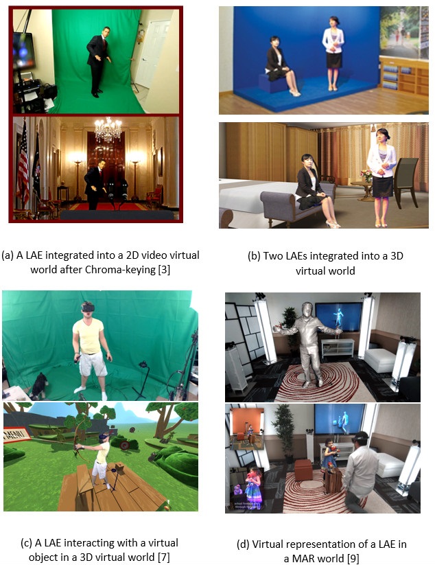
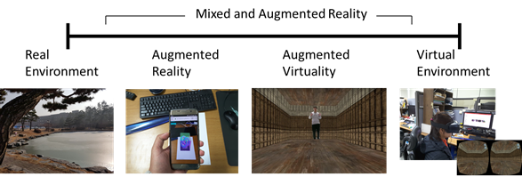
As illustrated in ISO/IEC 18039: Mixed and Augmented Reality (MAR) reference model, MAR represents a continuum that encompasses all domains or systems that use a combination of reality (e.g. live video) and virtuality representations (e.g. computer graphic objects or scene) as its main presentation medium [1,2]. Figure 1 illustrates the MAR that defined according to mixture of reality and virtuality representations. The real environment refers to the physical world environment where a LAE and objects are located. Augmented reality refers to the view of real world environment whose elements included LAE and objects can be augmented by computer-generated sensory. Augmented virtuality is the virtual environment that physical world elements included LAE can be mapped and interacted within. Virtual environment commonly refers to virtual reality that is the computer-generated realistic images and hypothetical world that replicate a real environment. A LAE wears an HMD devices to see the virtual world and interacts directly with virtual objects.
LAE Capturer and Sensor
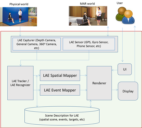
A LAE in a physical world can be captured from hardware and (optionally) software sensors that are able to measure any kind of physical property. As referenced in ISO/IEC 18039, two types of sensors, “physical world capturer” and “sensor”, are used to embed the LAE into the virtual world and to perform an interaction between the LAE and objects in the virtual world. The most common “physical world capturer” sensors are video and/or depth cameras which capture a physical world as a (depth) video containing live actors and entities. The video is used to extract the LAE and its actions to be processed by the recognizer and tracker components. The actions, especially, may affect interaction between the LAE in the physical world and objects in the virtual world. The target physical object can generate physical or nonphysical data which can be captured from a “sensor”. The (non) physical data can be used to detect, recognize, and track the target physical object to be augmented, and to process the interaction. The sensing data is input into the recognizer and tracker components.
Tracker and Spatial Mapper for a LAE
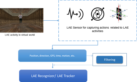
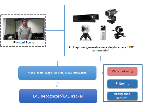
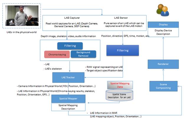
Figure 7 shows that a LAE, which is represented in the physical world, can be captured, and sensing data extracted, by a LAE capturer and LAE sensor. The sensing data that relates to the LAE from the LAE capturer and/or LAE sensor needs to be pre-processed in order to provide optimized sensing data for doing spatial mapping of the LAE in the MAR world. LAE capturer refers to physical world capturing devices, such as depth cameras, general cameras, and 360o cameras. The video, image, skeleton, and audio information will be parsed to a pre-processing function to compose the filtering, colour conversion, background removal, Chroma-keying, and depth information extraction by using the technique of computer vision. The results of pre-processing will be transmitted to a LAE tracker. Furthermore, the LAE sensor for capturing the event of the LAE’s motion, such as position, direction, geographic coordinate system sensing, time, and motion, will provide that sensing data to a filtering function. The filtering function is used for processing the sensing data and recognizing the target object. The raw signal for representing a LAE and target object specification data will be parsed to the LAE tracker. The LAE tracker can track a variety of information related to a LAE, such as real camera information and the LAE itself in the physical world [15].
Recognizer and Event Mapper for a LAE
Overview
Recognition can only be based on previously captured target signals. Both the recognizer and the tracker can be configured with a set of target signals provided by or stored in an external resource (e.g., a third party database server) in a manner consistent with the scene definition. The recognizer can be independently implemented and utilized. There are two types of data used by the recognizer: the output from the LAE capturer and the output from the LAE sensor.
Recognizer
After obtaining sensing data from the LAE sensor, the data will go through to the LAE recognizer for recognizing events of LAE gestures, object collision, and so on. The recognizer is a component that analyzes sensing data related to the representation of a LAE in a MAR world and produces MAR events and data activated from the LAE through comparison with a local or remote target signal (i.e., the target for augmentation) stored in the MAR scene.
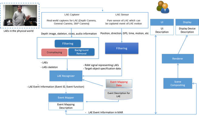
Figure 10 shows an event of gesture of a LAE in the physical world captured by the LAE sensor and the LAE capturer. After filtering the LAE’s raw data, the filtered data (position, orientation, direction, motion, etc.) will be parsed to the LAE recognizer for recognizing the specific target event. The LAE recognizer will be processed according to the event mapper and event description for the LAE. The event mapping data is stored in the event description for the LAE and can be used by the LAE recognizer according to the specific target and event_ID. The LAE’s event information, such as event_ID, event_type, and event function, will be parsed to the event mapper for mapping the event. By analyzing the LAE information, the event mapper will produce the MAR event in the MAR scene. The MAR event results from the detection of a relevant condition from the LAE in the physical world and augmentation. The event result will be parsed to the scene compositing module and renderer in order to render the event function for display and UI
The input and output of the recognizer are:
- Input: Sensing data related to the representation of the LAE in the MAR world. The input data model of the recognizer is the output of the sensors. The other input to the recognizer, the target physical object data, should contain the following elements: First, it should have an identifier indicating the event when the presence of the target object is recognized. Second, the target physical object specification may include raw template files used for the recognition and matching process, such as image files, 3D model files, sound files, etc. Third, it may include a set of feature profiles. The types of features depend on the algorithms used by the recognizer. For instance, it could be a set of visual feature descriptors, 3D geometric features, etc
- Output: At least one event acknowledging the recognition, which identifies the recognized target and optionally provides additional information that should follow a standard protocol, language, and naming convention.
|
Dimension |
Type |
Types |
|
Input |
Physical world |
• Camera information • 2D Chroma-keying image • Audio • Gesture |
|
Sensor |
• Sensor information |
|
|
Output |
Physical world |
• Event indication only of the recognized object • Event by gesture and audio information |
|
Sensor |
• Event indication only of the recognized object |
Event Mapper
The Event mapper creates the relationship to the MAR event of a LAE that is obtained from the LAE recognizer and/or LAE tracker. It describes the MAR event that can occur due to the controlling event (gesture, movement, head tracking, sensor, etc.) and the condition specified in the MAR scene. In order to map the MAR event within the MAR scene, as well as the events identified and recognized by the LAE recognizer, event_ID, event_type, and eventDB (event database) are needed. The event refers to the sequence of the controlling event of a gesture by the LAE. The gesturing data will be recognized by the LAE recognizer to determine the type of event, and then the event function will be retrieved from the eventDB.
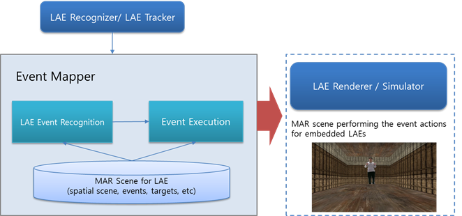
After retrieving the sensing data of the LAE, the event control model proposed in Figure 11 can be concretely developed with two modules, a recognition module and an execution module. Especially, the objective is to obtain faster and more accurate sensing data from the LAE itself and its handling devices in real time. If a hand gesture is used to control the events of a LAE, a depth camera, which allows skeleton images of one or two LAEs to be tracked, can be employed as a motion-sensing input device. Position information for the left and right hands can be obtained via depth. A position in 3D real space is represented by three Cartesian coordinates (x, y, depth) at each joint of the skeleton. An acquired position is first filtered to suppress image noise and then reprocessed with depth calibration and depth cueing to reduce image flickering. Depth supports some filtering features, but the resulting object boundaries remain very unstable and there is flickering. After all filtering processes have been carried out, hand gestures will be recognized by the recognition module, and the recognized event will be executed by the execution module in a virtual space, according to the gestures.
The event relationship between a particular recognition system and a target scene is provided by the MAR experience creator, and is maintained by the event mapper. The input and output of the event mapper are:
- Input: Event identifier and event information.
- Output: Translated event identifier for the given MAR scene
|
Dimension |
Types |
|
Input |
• Event Information • Event identifier (virtual camera control, virtual object control, AR content control) |
|
Output |
• Translated event identifier for the given MAR scene • Interaction of a virtual object event |
Events execution
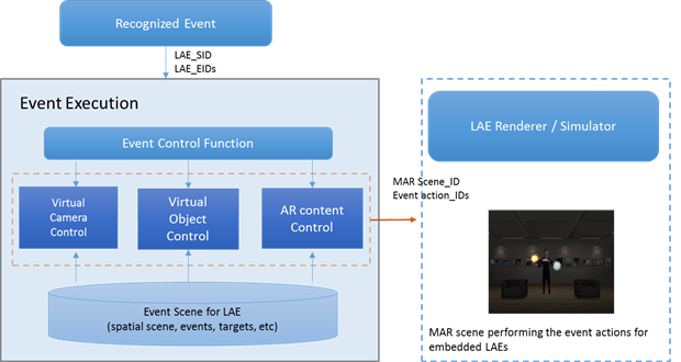
A detected event is transferred in the event class EventClass, in an execution module. If the detected event is one of the events defined in the MAR system, the event corresponding to the recognized event will be applied to the object in the 3D virtual space by the event executor EventExecutor. In other words, the object in the 3D virtual space will be manipulated according to the corresponding event function.
Figure 12 shows the structure for executing an event to control an object in a 3D virtual space. The class EventExecutor employs registered object-control functions to control objects in the 3D virtual space by analyzing events in EventClass. If a virtual object can be controlled by an event, the class EventExecutor is set as a member of the object instance, a callback function is created to be executed on the gesture event for the object, and the generated function is linked to a corresponding gesture delegate function in EventExecutor based on the event type. Then, when an event occurs, the MAR system executes the function executeCommand, to which the event is passed as an Event instance, and executes the generated callback function via the corresponding delegate function in EventExecutor. As a result, a LAE can interact with 3D virtual objects in a MAR environment just as it can with real-world objects.
Examples of LAE Recognizing and Event Mapping in MAR
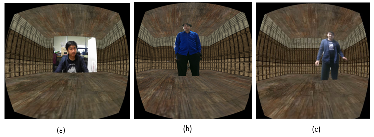
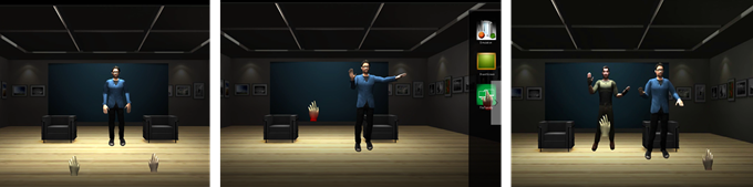
Figure 13 shows the interaction of a LAE with virtual objects in a MAR scene [16-17]. Examples of interactions include dancing on a virtual Dance Dance Revolution (DDR) [18] stage, dodging a piece of wood, and walking on a balance beam. If the LAE follows prescribed conditions accurately, they win the game, otherwise they lose. In the first example, the man moves (dances) in front of the camera, the motion is captured, and the music plays according to the motion of his feet. In the second example, the piece of wood is a virtual object in the 3D MAR world, and the man tries to dodge the object. If he is unsuccessful, a collision between his head and the virtual object will occur. In the third example, the man is walking in the physical world but it appears as if he is crossing a balance beam in the MAR scene. If he falls, an event will occur.
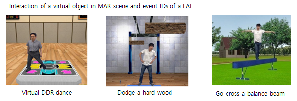
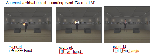
Figure 14 shows events of a LAE in a MAR world based on recognition of gestures and event IDs [19]. The man is embedded into the MAR world by applying the spatial mapper and filtering with the Chroma-keying function to remove the background. The man can use his hands to create and control the events in the MAR world by doing hand gestures. The gestures are recognized by the LAE recognizer. The event IDs are retrieved from the eventDB and mapped with a module/function in the MAR scene by event mapping. An event occurs based on an event_ID, such as lifting the right hand creates fire, or lifting two hands creates both fire and ice, or holding the hands together makes the fire disappear.
Scene Representation for a LAE
Overview
MAR scene refers to a scene that represents a virtual scene and placeholders. It serves as the implementation structure that combines the physical world scene/objects and the virtual scene/objects. It is the observable spatiotemporal organization of physical and virtual objects that have been tracked and recognized by the LAE tracker and LAE recognizer functions. The scene representation can be based on several proposed AR related formats so far [20-25].
An event of a LAE can occur based on the LAE’s own actions, as well as based on output obtained from sensing interface devices handled by the LAE. The LAE will be captured from general cameras and/or depth cameras. Its actions can be obtained by recognizing LAE sensing data. Meaningful events to be used in the MAR world can be classified into one of two types: sensing data by the LAE itself, or sensing data of devices handled by the LAE. The defined events will be stored in the eventDB.
- Sensing outputs captured from a “physical world capturer”
- Gestures – hands, fingers, head, body
- Facial expressions
- Speech and voice
- Sensing outputs captured from a “sensor” for the LAE
- AR marker
- Global Positioning System (GPS[1])
- Remote Wii motion data
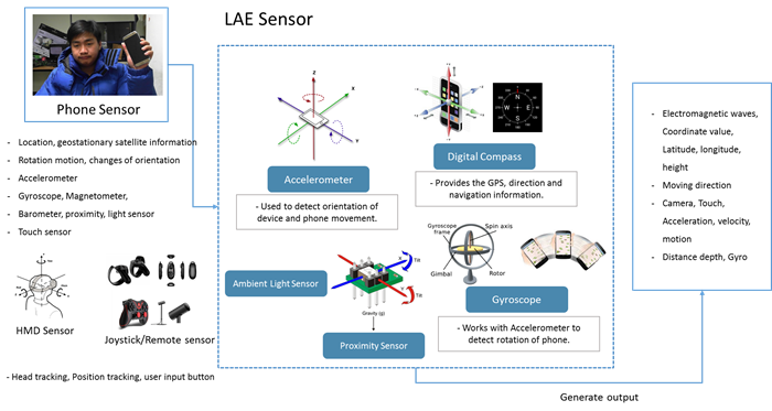
- Other sensing data by a smart device: three-axis accelerometer, magnetometer (digital compass)
Sensing data will be used to define the events of the LAE. We assume that a virtual camera, a virtual object, or an AR object in a 3D virtual space is controlled by human body gestures of the LAE. To define the gestures more efficiently, basic primitive postures of a human body are defined, as shown in Figure 15. The postures consist of position, vector, image, and skeleton. By detecting the postures of a human body and combining them, gestures can be defined. We define three common primitive gestures of a human body: linear, wave, clockwise/counterclockwise. A variety of events for a human body can be defined using these predefined primitive gestures.
A MAR scene describes all the information of a LAE that relates to a MAR world and consists of a virtual scene, sensing data, spatial scene, events, targets, etc. The MAR scene representation is the middleware of the spatial mapper and event mapper, which observes the spatial of physical objects, virtual objects, and events. A MAR scene has at least one physical object and one virtual object.
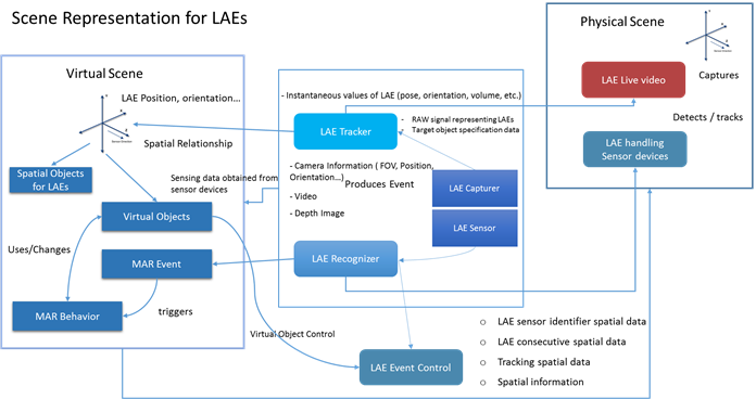
Figure 15 shows the scene representation for handling a LAE in a MAR world. After receiving sensing information from the sensor, the RAW signal representing the LAE and target object’s specification data will be parsed to the LAE tracker and LAE recognizer. Thus, the LAE and physical world objects can be captured and detected. The LAE’s information can be calculated and mapped in the virtual scene according to the LAE’s position, orientation, etc. Calibration and spatial mapping between real and virtual objects are needed in a MAR scene. A physical world object is mapped to a placeholder in the MAR scene by, e.g., image feature, marker pattern definition, or geographic coordinate system, and provides the information data/method to recognize and track the object for semantic information as to what the object actually is. The video of the entire scene, including the background, will be processed in a background removal function to extract the LAE and its information. The LAE is embedded in the virtual scene via real time streaming, and the virtual objects of the virtual scene can be interacted with by the LAE’s gesture/event according to the event of the LAE recognizer. When there are changes to a virtual object, MAR behavior will invoke the MAR event and the LAE recognizer will recognize then produce the event.
Sensor/device parameters are important for correctly presenting a MAR scene, e.g., the relationship of a physical world capture sensor parameter to the MAR scene viewpoint and image scale. The viewpoint and image scale must be changed according to the information captured by the physical world capture sensor.
Scene Description
MAR scene description will be used to perform more effective spatial mapping and event handling of a LAE in a MAR world. Two types of scene description will be provided.
First, spatial mapping is used for mapping spatial relationship information between a physical world and a MAR world. It describes how a LAE in the physical world can be mapped into a MAR system. LAE information provided by the LAE tracker and/or LAE recognizer will set a LAE ID and initialize the spatial mapping information. The spatial reference frames and spatial metrics used in a given sensor need to be mapped into the MAR scene so that the LAE mapping object can be correctly placed, oriented, and sized. The spatial mapping information can be modelled as a table, with each entry characterizing the translation process from one aspect (e.g. lateral unit, axis direction, scale, etc.) of the spatial property of the sensor to the given MAR scene [5].
|
LAE ID |
Initial spatial mapping information |
LAE mapping object |
Spatial mapping function |
|
LAE_ID |
Position, orientation, etc. |
Virtual 2D/3D object |
Spatial mapping from physical world to MAR world |
Second, event mapping describes how a LAE in a MAR world can produce an event, such as interaction, gesture, movement, voice recognition, etc. It creates an association between a MAR event obtained by the LAE recognizer and/or LAE tracker and a condition specified in the eventDB. For example, a LAE in a MAR world can use its hands to control/interact with virtual objects by doing hand gestures (palms up/down, hands clutched, hands raised, etc.). An event will occur when the LAE does the gesture or movement or handles a sensing device (e.g., smartphone, joystick, etc.). The sensor device handled by the LAE can generate the sensing data for creating an event in the event mapper. Event mapping matches the sensor_id and event_id which is retrieved from the eventDB. Then, it will know the type of event and call a function to be executed.
|
LAE ID |
Event ID |
Event Type |
Event Function |
|
LAE_ID |
Event_id |
Event_type |
Event call functions |
Renderer
Overview
Rendering refers to the process of generating data from a 2D/3D model, updating a simulation, and rendering the presentation output for a given display device. After the processes of the spatial mapper and event mapper have completed, the data will be parsed to the renderer. Thus, the renderer has the job of rendering LAEs, virtual objects, and events to a display device.
Rendering of a LAE in a MAR system needs to be done based on the type of display, such as Web rendering to a browser, or PC, mobile, and stereo rendering. Stereo rendering has to do with the stereoscopic separation of the left and right eye. Rendering needs to be smooth and in real time, based on the user’s HMD.
There are two issues when it comes to rendering. The first has to do with spatial mapping rendering, which refers to a LAE being embedded into a MAR scene. Based on the embedding process, the renderer needs to generate a high quality and smooth display. The second has to do with event mapping, which refers to the events of a LAE, such as natural movement rendering, gesture, voice recognition, and so on. The renderer needs to render the event perfectly in order to produce a quality, streamlined event. That is, when a LAE moves or does gestures, this should be reflected in the MAR world in a streamlined fashion. Furthermore, the renderer needs to control problems that might occur during LAE movement, such as moving to an unacceptable position and orientation, or gestures and movement being too slow, which may result in low quality rendering.
Computational View
A MAR system can specify various capabilities of the renderer, so a scene can be adapted and simulation performance can be optimized. The rendering of virtual reality, a stereoscopic HMD, and a mobile device might require different rendering performance. Multimodal output rendering might necessitate careful millisecond-level temporal synchronization. The output is a visual, aural, and/or haptic stream of data (such as a video frame, stereo sound signals, etc.) to be fed into a display device.
Information View
The input and output of the renderer are:
- Input: MAR scene graph data
- Output: Synchronized rendering output (e.g., visual frame, stereo sound signals, motor commands, etc.)
The renderer can be categorized in the following way:
|
Dimension |
Types |
|||
|
1. Modality |
Visual |
Aural |
Haptics |
Others |
Renderer
Display refers to a hardware component that produces the actual presentation of a MAR system for representing a LAE to the end user. Displays include monitors, HMDs, projectors, scent diffusers, haptic devices, sound speakers, etc. The display needs to meet specific requirements in order to provide a good quality display to the end user. An actuator is a special type of display that does not directly stimulate the end user’s senses but rather produces a physical effect in order to change properties of physical objects or the environment.
A UI is a component of hardware used to capture user interactions (e.g. touch, click) for the purpose of modifying the state of a MAR scene. A UI requires sensors to achieve this purpose. There are many types of UI sensors for capturing user interactions, such as gesture, voice, haptic, gyro, and so on. These sensors have a usage similar to that of LAE sensors. However, the difference is that, for UI sensors, the only physical object sensed is the user.
There are two kinds of events that can be generated:
- - A LAE can generate events by itself – the LAE uses gestures, voice, head movements, etc.
- - A LAE can handle a device for generating events – the LAE can use a smartphone, haptic, joystick, etc.
- The input and output of the display are:
- Input: Rendered signals
- Output: Display output
- The input and output of the UI are:
- Input: User action, gesture, voice, interaction
- Output: UI event
Extensions to Virtual LAE
Virtual LAE refers to a virtual representation of a LAE which is captured by 3D capturing technology and that can be reconstructed in a MAR world. The virtual LAE appears as a real person that can be communicated with, though it is not. Figure 16 shows a virtual LAE restricted to and communicating in a MAR world. The virtual person is reconstructed and displayed in the MAR world as a virtual object. Recently, a new type of 3D capture technology is appearing so that it allows a high-quality 3D model of a person to be reconstructed, compressed, and transmitted anywhere in the world in real time [4]. When combined with a mixed reality display, this technology allows a user to see, hear, and interact with a remote participant in 3D as if they are actually present in the same physical space. Communicating and interacting with a remote user becomes as natural as face-to-face communication.
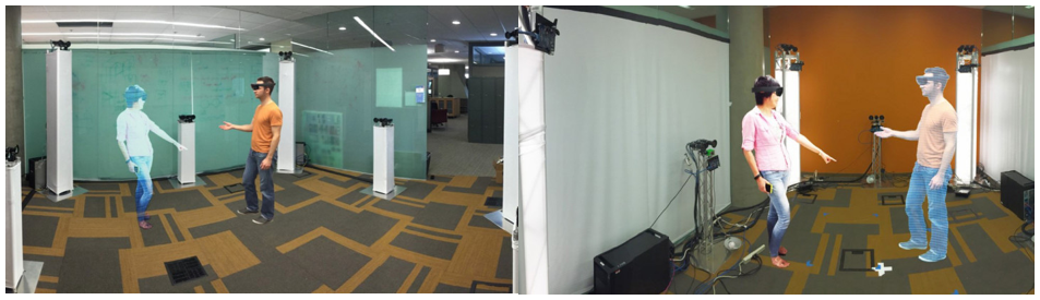
An HMD device is required to view the hologram in real time, and a room surrounded with 3D cameras is necessary to create the hologram. The virtual LAE is not viewable without wearing an HMD device, and it is not possible to make eye contact with someone who is wearing the device.
A second type of virtual LAE refers to a virtual character (avatar) that is represented in a MAR world, as shown in Figure 17. This kind of virtual LAE can be used instead of a LAE in a physical scene. However, the interaction and motion of the virtual character must be accomplished by LAE gestures in the physical scene. The avatar can be represented along with other avatars, and the avatars can be made to communicate with each other. An avatar can be constructed with a 3D model, and points, like a LAE skeleton, need to be defined in order to produce animation and gestures. The virtual character and movements must be transmitted in real time using a LAE and movements in the physical scene, such as gestures of the hand, foot, head, and mouth.
System Performance
System performance for a MAR LAE is an important part of the user’s experience. The performance of a MAR LAE system can be evaluated in measurable and technical terms. Performance is based on sensor quality, quality of LAE expression, processing speed, response time, latency, dirty chroma-keying results, frame rate, and so on. Sensor refers to a LAE sensor, which is a sensor for capturing a LAE. The accurateness of the sensor affects the accuracy and quality of the LAE’s information. The expression of the LAE can also be affected by system performance related to applying a Chroma-keying function, background removal, natural movement, and degree of freedom.
Latency can be measured as the total time needed to process the target object and produce the augmentation, i.e. the time delay between the cause and the effect of a physical change in the system being observed. It is a result of the limited velocity with which any physical interaction can take place. For example, the physical world LAE moves to the left, but the system update is slow and the LAE still shows at the right.
Augmentation precision can be measured as the error between the virtual camera parameters estimated by the tracker and the correct ones, or as the distance (in pixels) and angular distance (in degrees) between where the virtual object is displayed and where it should be displayed.
Operating conditions affecting performance may include lighting conditions, the mobility of the target object, sensing distance, orientation, etc.
Response time, which is the total amount of time it takes to respond to a request for any functionality, such as correlation detection, object control, 3D display rendering, etc., is another consideration. There are three types of response time: The first, service time, refers to how long the MAR system takes to respond to a request. The second, waiting time, refers to how long a request has to wait for another request queued ahead of it before it can run. The third, transmission time, refers to how long it takes to process the request and respond back to the requestor. Examples of requests include gestures for interacting with objects, a LAE’s movement (updating position and movement in virtual space), etc.
Safety
A LAE in a MAR world can be presented with various safety issues, as it is a human being acting in the physical world. Thus, a LAE’s attention needs to be focused. LAE safety guidelines are necessary to ensure that LAE in a MAR world content includes components for safeguarding the LAE during system operation. These safety guidelines can be used to reduce the risk for a LAE by considering the following:
- Dangerous obstructions that could lead to injury during the LAE’s performance in the MAR world
- Any information that needs to be encrypted for security reasons
- Personal privacy of the LAE and potential exposure of personal information to unauthorized systems or third parties via a sensor/camera being out of scope, including authentication identity, system access to a LAE’s personal data, etc.
- Due consideration of the physical world situation during LAE movement in the MAR world
- Virtual reality sickness from wearing an HMD
- Wearing an HMD device and being blind to potentially dangerous objects in the vicinity
- Avoiding quick acceleration or deceleration of camera movements, and using a constant velocity instead
- Keeping the frame rate up (less than 30fps is uncomfortable)
- Intermittent disconnection of the network service,leading to false confidence in the currently presented information
- Avoiding the use of Depth of Field or Motion Blur post processing because of not knowing where the eyes will focus
- Avoiding sharp and/or unexpected camera rotations
- Avoiding brightness changes (use low frequency textures or fog effects to create smooth lighting transitions)
Conformance
Conformance for LAE representation in a MAR world is expressed around the aspects of how a LAE can be embedded into a MAR world and the implementation process related to the LAE. The conformance of LAE representation to this standard shall satisfy at least the following requirements:
- The key architectural components that shall be present for LAE representation are the following:
- LAE capturer
- LAE sensor
- LAE tracker
- Spatial mapper
- LAE recognizer
- Event mapper
- Scene representation
- Renderer
- Display and UI
- The implementation of LAE representation in a MAR world shall conform to section 4 that describes the concepts and architectural components for implementation as shown in figure 3.
- A LAE in the physical world can be captured by a LAE capturer and sensor; then doing chroma-keying, filtering, tracking, and recognizing the LAE information as specified in section 5.
- The relationship among the components and implementation of a LAE that can be mapped, moved, and interacted virtual objects naturally within MAR world according to spatial mapper, event mapper, and scene description shall conform and specify in section 6 and section 7. The scene for combining the physical and virtual world shall conform to section 8.
Annex A. Use Case Examples
A.1 3D Virtual Studio
There are many examples where a LAE can be embedded into a MAR world. The first example is of a virtual broadcast studio. Figures 18(a) and (b) show a LAE as an announcer integrated with two different virtual broadcast studios. In order to visualize the LAE in the studio, the MAR system captures the image, including the LAE, by a general camera, removes the background of the image by processing Chroma-keying for the captured image, and then renders the 3D virtual world in which the image (with the background removed) is inserted by performing texture mapping on a polygon. Here, the polygon is a movable region of the LAE.
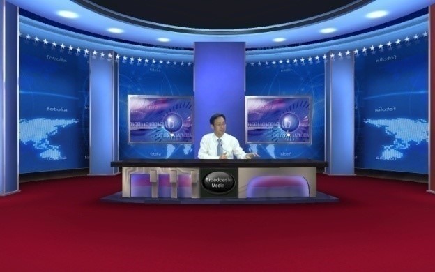
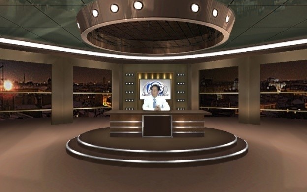
Figure 18. Two different virtual broadcast studios including a LAE
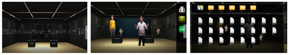
A second example, in Figure 19, is of a LAE walking into a 3D virtual gallery and taking a seat. Rendering of the LAE is done as described above.
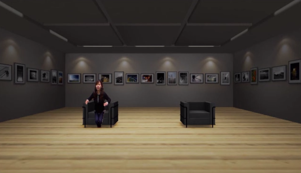
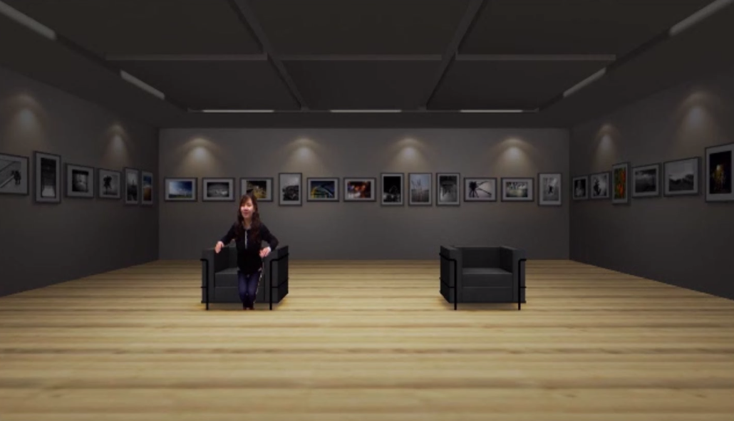
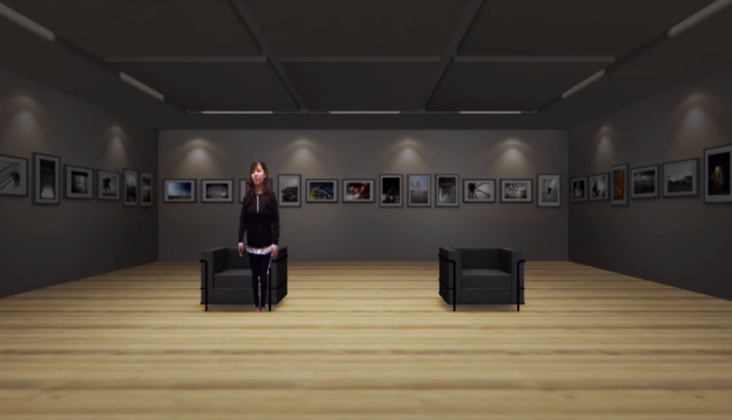
Figure 19. A LAE taking a seat in a 3D virtual gallery
A.2 Event Mapping of a LAE in a MAR world
There are many types of sensing interfaces between a LAE and a 3D virtual world. In this document, we consider hand gestures of the LAE itself. As proposed in the standard, three different types of content - virtual cameras, virtual objects, and virtual AR objects - in the 3D virtual world can be controlled through these predefined hand gestures.
Control of an interactive virtual camera by a LAE
A virtual camera in 3D virtual space can be controlled by the hand gestures of a LAE in a physical world. The movement and positions of the hands of a LAE can be obtained from a depth camera, which is a motion sensing input device used to capture position information for tracking a user’s skeleton images. Positions are presented as the location (x, y, depth) at each joint point of the skeleton from the depth camera. Even if the depth input device processes filtering for the captured positions, flicker in the sequence of positions can still occur. Two operations, depth calibration and depth cueing, for the sequence of positions are done in a pre-processing step in a MAR system to reduce flicker.
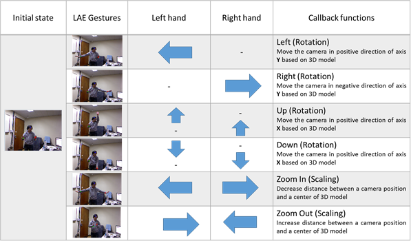
To more accurately recognize the hand gestures of a LAE, the active space in which the hand gestures are performed is continuously monitored. A virtual camera will be moved according to the results of recognition of gestures in a valid subspace. Two hands, left and right, will be used to control the virtual camera in the MAR system. Twenty-four types of hand gestures can be created, based on four movement vectors - upper, lower, left, and right - of the two hands, combined. When the two hands are moved independently into place, 16 (= 4x4) gestures can be created; when one hand is fixed and the other is moved, 8 (= 2x4) gestures can be created; for a total of 24. In a MAR system, only six of the 24 gestures will be defined, as shown in Table 10.
| Gesture Types | Explanation |
| G1(left rotation of a camera) | Actions of moving the right arm to the right direction, while holding the left arm. |
| G2(right rotation of a camera) | Actions of moving the left arm to the left direction, while holding the right arm. |
| G3(up rotation of a camera | Actions of moving both the left and right arms to the up direction. |
| G4(down rotation of a camera) | Actions of moving both the left and right arms to the down direction. |
| G5(zoom-in of a camera) | Actions of outstretching both left and right arms. |
| G6(zoom out of a camera) | Actions of pursing both left and right arms |
In order to simulate the six events using hand gestures of a live actor and entity, gestures events as shown Figure 14 can be defined with the movements of two hands. For an example, a left rotation of a virtual camera will be performed by recognizing that a left hand moves in the left direction and a right hand is fixed. In order to do the recognition more better, we assume that center position of a virtual camera, which is always looking to the origin of the 3D virtual space with fixed up vector, can be placed at any location of the 3D virtual space. In this situation, the center position will be transformed according to actions of the suggested gestures. To simulate naturally the movement of the camera, first of all, we have to consider the movement of gestures. Assume that the current position of a hand is located at any position in a 3D virtual space. When the movement position of the hand is escaped out of the designated circle with its center and its radius, the movement will be detected and one of four locations, left, right, up, and down which are defined according to the relative position from the located position will be returned.
A LAE performs one of six types of gestures to control a virtual camera in a 3D virtual space while viewing a rendering scene. Figure 21 (a) shows the result of applying a gesture to left rotate the center position of the virtual camera, after designating the initial position of the LAE. Similarly, Figure 21 (b), (c), (d), (e), and (f) show the results for right rotation, up rotation, down rotation, zooming in, and zooming out, respectively.
(a) left rotation
(b) right rotation
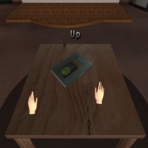
(c) up rotation
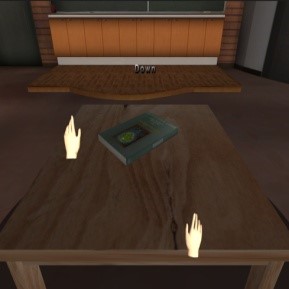
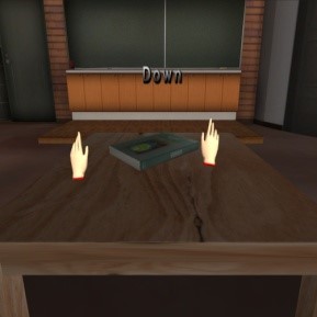
(d) down rotation
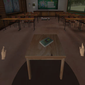
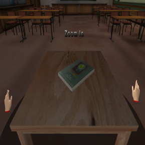
(e) Zoom In
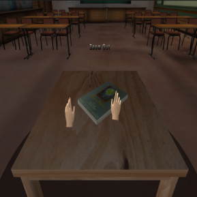
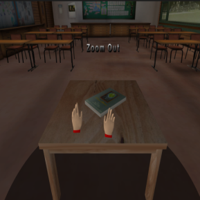
(f) Zoom Out
Figure 21. Examples of applying hand gestures to control a virtual camera in a MAR system [19]
A.3 Interactive controlling of a virtual object in a MAR world by action of a live actor and entity
Hand gestures of a LAE are able to control virtual objects in 3D virtual environments in a manner similar to the virtual camera control described above. The hand gestures can be obtained by using a depth device. With the movement of two hands, seven gesture events can be defined, as shown in Figure 22. For example, right rotation of a virtual object will be performed by recognizing that the right hand moves to the right, while the left hand is fixed.
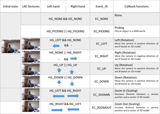
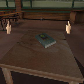
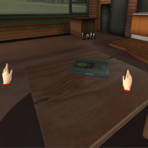
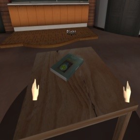
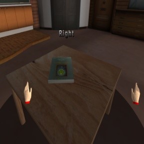
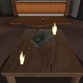
Figure 23 shows a simulated replacement of a flat tire on a virtual car with a spare tire from the car’s trunk. Figure 23 (a) shows the initial 3D virtual space in which the car is located, together with flesh-colored virtual left and right hands ready to perform gestures to control the car (virtual object). When the LAE’s hand is located in the inactivation area, or when no gesture is being made, the virtual hand remains flesh colored. If the LAE’s hand enters the activation area, the virtual hand begins to turn red. When the virtual hand turns completely red and is surrounded by four arrow keys, this indicates that the gesture recognition system has begun to recognize the hand gesture, as shown in Figure 23 (c). If the LAE’s hand enters an object-selection area, the virtual hand begins to turn blue. When the virtual hand turns completely blue and is surrounded by four arrow keys, this indicates that the virtual object in the vicinity of the virtual hand is selected and is ready to be manipulated via real-world hand gestures. To replace the flat tire, we need to remove the flat tire, open the trunk, extract the spare tire, and set it on the ground. In Figure 23 (d), the blue hands hold the spare tire and push it closer to the car. The tire is then set upright with the left hand and attached to the wheel of the car. Thus, a virtual flat tire on a virtual car in a virtual space is replaced with a virtual spare tire from a virtual trunk. Figure 24 (e) shows an example of opening a door on the car and taking a seat, and then, in Figure 24 (f), controlling the audio system while seated. Figure 24 (g), (h), and (i) show an example of simulated engine disassembly.
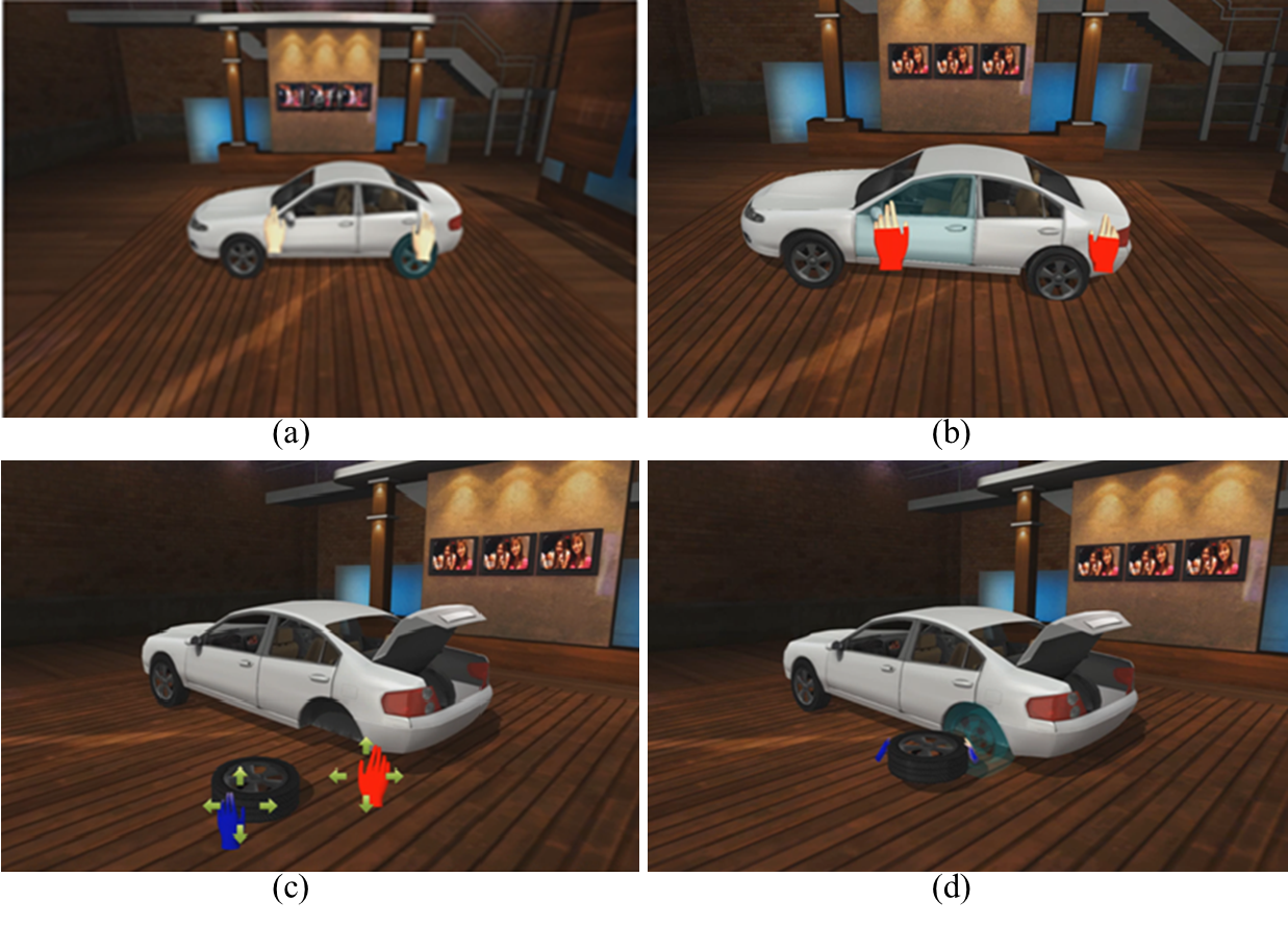
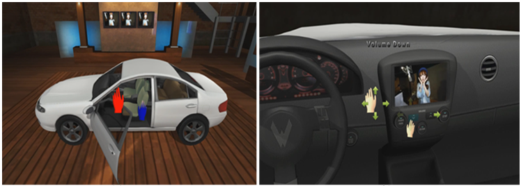
When the LAE’s hand is located in the inactivation area, or when no gesture is being made, the virtual hand remains flesh colored. If the LAE’s hand enters the activation area, the virtual hand begins to turn red. When the virtual hand turns completely red and is surrounded by four arrow keys, this indicates that the gesture recognition system has begun to recognize the hand gesture, as shown in Figure 23 (c). If the LAE’s hand enters an object-selection area, the virtual hand begins to turn blue. When the virtual hand turns completely blue and is surrounded by four arrow keys, this indicates that the virtual object in the vicinity of the virtual hand is selected and is ready to be manipulated via real-world hand gestures. To replace the flat tire, we need to remove the flat tire, open the trunk, extract the spare tire, and set it on the ground. In Figure 23 (d), the blue hands hold the spare tire and push it closer to the car. The tire is then set upright with the left hand and attached to the wheel of the car. Thus, a virtual flat tire on a virtual car in a virtual space is replaced with a virtual spare tire from a virtual trunk. Figure 24 (e) shows an example of opening a door on the car and taking a seat, and then, in Figure 24 (f), controlling the audio system while seated. Figure 24 (g), (h), and (i) show an example of simulated engine disassembly.
A.4 Augmenting a real object with special effects
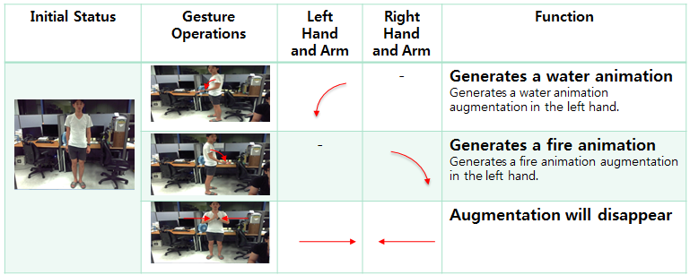
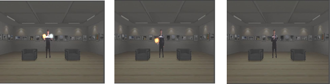
Gestures of a LAE are able to augment virtual objects in 3D virtual environments in a manner similar to the other operations described above. The gestures can be obtained by using a depth device. Three gesture events can be defined with the movement of two hands and two arms, as shown in Figure 25. Figure 26 shows examples of using these three gestures. To augment the scene with a water animation, the left arm is bent and the left fingers are spread. Similarly, to augment with a fire animation, the right arm is bent and the right fingers are spread. The animations will continue until the disappearing gesture is recognized - in this example, by bringing the hands together.
A.5 3D Virtual Conference
Virtual conferencing and virtual presentations are other applications of a MAR system. LAEs can hold a conference or deliver a presentation in a 3D world. They can broadcast to join the conference in real-time, and embed themselves (as LAEs) into the 3D virtual wold. Multiple LAEs are able to move, communicate, open presentation files, watch videos, and interact with virtual 3D objects in the 3D virtual conference room.
Bibliography
[1] Milgram, P., Takemura, H., Utsumi, A., and Kishino, F., Augmented reality: A class of displays on the reality-virtuality continuum, Proc. of Telemanipulator and Telepresence Technologies, 1994, pp. 2351–34.
[2] Azuma, R., A survey of augmented Reality, Presence: Teleoperators and Virtual Environments,
6 (4), 1997, pp. 355 - 385.
[3] Chroma key – https://en.wikipedia.org/wiki/Chroma_key.
[4] Jolesz, F., Image-guided procedures and the operating room of the future, Radiology, 204(3), 1997, pp. 601-12.
[5] Billinghurst, M., Kato, H., and Poupyrev, I., The MagicBook: A transitional AR interface, Computers and Graphics, 25 (5), 2001, pp. 745-753.
[6] Fuchs, H., Livingston, M., Raskar, R., Colucci, D., Keller, K., State, A., Crawford, J., Rademacher, P., Drake, S., and Meyer, A. Augmented reality visualization for laparoscopic surgery, Proc. of Intl. Conference on Medical Image Computing and Computer Assisted Intervention, 1998, pp. 934-943.
[7] Mixed Reality VR testing – Bowslinger & Holoball https://www.youtube.com/watch?v=Kw5yPyv9O9E.
[8] Kato, H. and Billinghurst, M., Marker tracking and HMD calibration for a video-based augmented reality conferencing system, Proc. of Intl. Workshop on Augmented Reality, 1999, pp. 85-94.
[9] Microsoft Holoportation – https://www.microsoft.com/en-us/research/project/holoportation-3/.
[10] OpenCV, http://code.opencv.org, 2017
[11] WebVR, http://www.webvr.info, 2017.
[12] WebVR Concept, https://developer.mozilla.org/en-US/docs/Web/API/WebVR_API/WebVR_concepts, 2017.
[13] Chheang Vuthea, Ga-Ae Ryu, Sangkwon Jeong, Gookhwan Lee, Kwan-Hee Yoo, A Web-based System for Embedding a Live Actor and Entity using X3DOM, Korean society of broadcast engineers, 2016, pp. 1-3.
[14] Jeon, S. and Choi, S., Real stiffness augmentation for haptic augmented reality, Presence: Teleoperators and Virtual Environments, 20(4), 2011, pp. 337-370.
[15] Klein G. and Murray, D., Parallel tracking and mapping for small AR workspaces, Proc. of Intl. Symposium on Mixed and Augmented Reality, 2007, pp. 1-10.
[16] Thomas, C., Close, B., Donoghue, J., Squires, J., De Bondi, P., Morris, M., and Piekarski, W., ARQuake: An outdoor/indoor augmented reality first person application, Proc. of Intl. Symposium on Wearable Computing, 2000, pp. 139-146.
[17] Lavric, T., Scurtu, V., and Preda, M. Create and play augmented experiences, Presentation from the 104th MPEG meeting, Inchon, 2014.
[18] Johanna H., International Survey on the dance dance revolution game, Retrieved January 29, 2015
[19] Jong-Oh Kim, Mihye Kim, and Kwan-Hee Yoo, Real-Time Hand Gesture-Based Interaction with Objects in 3D Virtual Environments, International Journal of Multimedia and Ubiquitous Engineering, 2013, pp. 339-348.
[20] MPEG ARAF: Augmented magazine and printed content, www.youtube.com/watch?v=CNcgxEOt_rM, 2015.
[21] ISO/IEC 23000-13, MPEG Augmented reality application format, 2014.
[22] Open Geospatial Consortium (OGC), Keyhole Markup Language (KML), www.opengeospatial.org/standards/kml, 2015.
[23] Mobilizy, ARML (Augmented Reality Markup Language) 1.0 Specification for Wikitude, www.openarml.org/wikitude4.html, 2015.
[24] Hill, A., MacIntyre, B., Gandy, M., Davidson B., Rouzati, and H. Khamra: An open KML/HTML architecture for mobile augmented reality applications, Proc. of Intl. Symposium on Mixed and Augmented Reality, 2010, pp. 233-234.
[25] ISO/IEC NP 19710, JPEG AR, 2014.